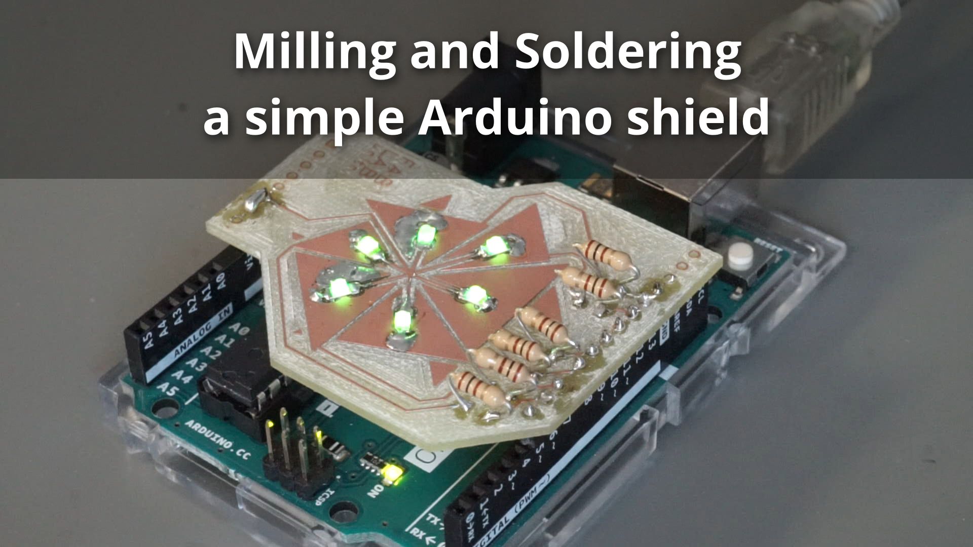
In this project we’ll create a simple single-sided PCB (printed circuit board) that functions as an “Arduino Shield” and lets us control six LEDs individually.
You can find the files for this project in the corresponding Drive folder.
Step 1: Design
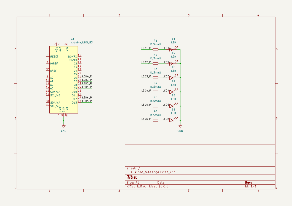
The PCB can be designed using KiCad, a free tool for designing electronics projects. The first step is to create the Schematic, which is a technical drawing that describes the functioning of the circuit, but without worrying about the details of its fabrication: we choose which types of components to use and how to connect them, but not what sizes they have, where they will be placed, etc.
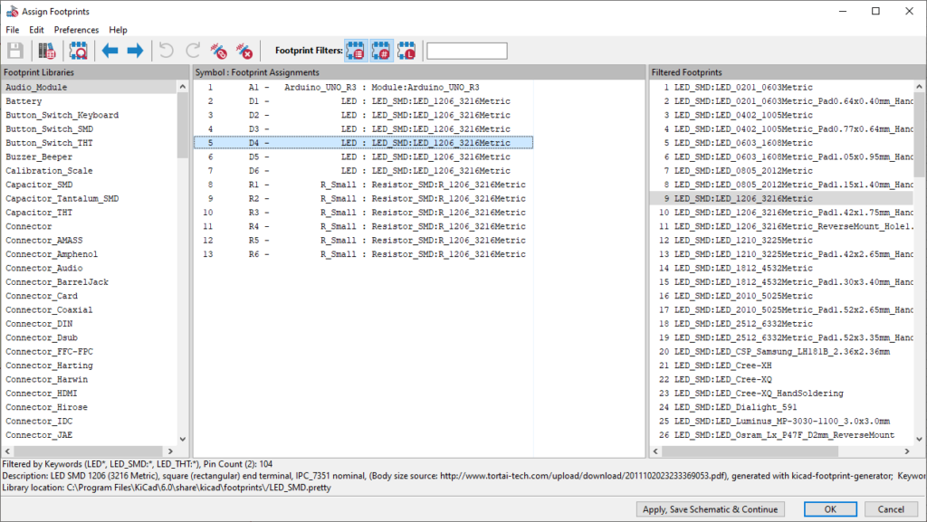
With the schematic done, we can run the “Footprint Assignment Tool” to choose the concrete sizes that we want to use for our components:
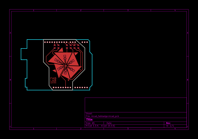
And finally we can move to the PCB Editor and create the PCB Layout for our project. After importing the parts using “Update PCB with changes made to Schematic”, we can arrange our components and use the track, via, fill etc. tools to connect everything according to the schematic. The Ratsnest will show us what to connect where using helper lines.
Once the layout is done, we can verify that it corresponds to our Schematic and that no errors have been introduced using the ERC (Electrical Rules Check).
Step 2: Toolpath Generation
To generate the Toolpaths that the CNC Mill can follow, we’ll use mods CE, and in particular the “programs > machines > Roland > SRM-20 mill > PCB CBA” program:
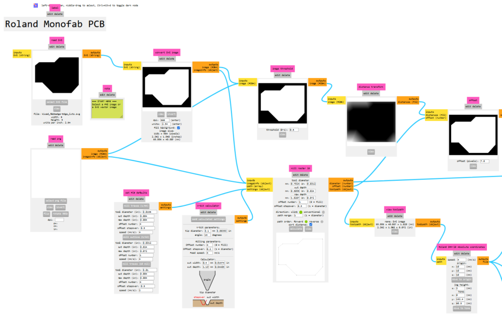
To use mods, we’ll need either SVG or PNG files of the “Edge.Cuts” and “F.Cu” layers, which can be exported from KiCAD. The files should be black and white, with the black part being the material to remove and the white part being the material to keep. If the colors are reversed, the “invert” buttons can be used to flip them so that the shapes are a white board on a black background.
Now the milling parameters can be set up and the toolpath calculated. If everything looks good, to export:
- Set the “origin” X/Y/Z values to 0
- enable the “on/off” switch next to the “save file” option
- press “calculate” again to download the .rml file
Step 3: Milling
Now we can use the generated .rml or .nc files with the VPanel tool to run our three passes. Before the first pass, we need to set our XY and Z home positions. After that, we have to set our Z home position again each time we change the tool to make sure everything is aligned.
Step 4: Soldering
Using a soldering iron and a vice to hold the PCB, we can solder the various components to the board. For most components it’s easiest to use the “tack soldering” technique, which consists of the following steps:
- Wet one of the PCB pads with solder
- Position the component using tweezers while melting the solder on the pad with the other hand.
- Remove the soldering iron and keep the component in place.
- After a few seconds it should be fixed in place. If it is not aligned properly, reheat and adjust the position.
- Solder the pad furthest from the “tacked” pad, then continue soldering any remaining pads.
- Reflow the first “tacked” pad, adding a little bit of solder or flux, to strengthen the joint.
Step 5: Testing & Using
Before hooking up a more complex circuit, it’s a good idea to test it to avoid damaging any other systems it will be connected to. Depending on the cirucit, different testing techniques can be used:
- Using a Multimeter to check for shorts (especially between power nets)
- Using a Current-Limited Power Supply to avoid damaging components
- Using a Multimeter to check voltage levels (especially power nets)
- Using an Oscilloscope to check individual signals of the circuit
In this case we use a current-limited power supply to test the circuit works as expected without risking to burn out any LEDs or an Arduino. Once everything is verified, we can attach our shield to an Arduino and start coding our animation:
Here’s the Arduino code for the animation shown in the video. You can also find the Arduino project in the files linked above.
int LED_PINS[] = { 9, 8, 7, 6, 13, 12 };
const size_t LED_COUNT = 6;

uint8_t state[LED_COUNT];

void setup() {
  for (size_t i = 0; i < LED_COUNT; i++) {
    pinMode(LED_PINS[i], OUTPUT);
    digitalWrite(LED_PINS[i], LOW);
  }
}

void loop() {
  size_t i = 0;
  size_t skip = 0;
  while (true) {
    state[i] = !state[i];
    digitalWrite(LED_PINS[i], state[i]);
    delay(100);
    i = (i + 1) % LED_COUNT;
    if (i == skip) {
      i = (i + 1) % LED_COUNT;
      skip = (skip + 1) % LED_COUNT;
    }
  }
}